Microphone capture firmware and a sonar transmitter design
I wrote code for a small chip that records two microphones in sync, 48,000 times a second, and researched a sonar transmitter for underwater robots. Team of 6, early stage.
Published 24 Aug 2026 · Updated 31 Oct 2026
- My part
- Microphone capture firmware and test scripts; sonar research, underwater-robot study and review brief (1 of 6)
- Team
- 6 · Aniruddha Kadam, Arya Maddel, Jagdish Sonigra, Kashish Degaonkar, Parth Latke, Tanish Thakkar
- Timeline
- Sep 2026 – now
- For
- Two defence briefs: speech in noise, and an adaptive sonar transmitter
- Status
- Ongoing: microphone capture works; no noise-reduction model or transmitter board yet
- Skills
- Embedded C · STM32 · ESP32-S3 · I²S and DMA · USB · Python (NumPy) · technical research
- Links
- Video (6 min) · code in a private team repository, available on request
- Skills
- Edge and low-resource systems, Embedded C · STM32 · Arduino
In short
- Problem
- Two defence problems: clean up radio speech buried in gunfire, engine and wind noise on a small device, and a sonar that changes each ping to suit the water without draining the battery.
- What I did
- Wrote code for a small chip that sends one or two microphones' sound to a laptop, scripts that test the recordings, and the research and design for the sonar transmitter.
- Result
- Two microphones recorded in sync, 48,000 times a second, closely matching each other (0.83 out of 1, 2 runs). No noise-reduction score yet: an electrical hum must be fixed first.
- How to check
- Video (6 min). Firmware, test scripts and measurement notes are in a private team repo; available on request. Raw recordings are kept locally.
The problem: two defence briefs, both judged on real hardware
Sep 2026
Our team of 6 took on two defence engineering briefs.
Speech in noise. Radio speech in defence settings is buried in gunfire, artillery, rotor and engine noise. The brief asks for AI-based noise cancellation that runs in real time on a small embedded device and reaches 3 targets: SNR above 15 dB, STOI above 0.85 and PESQ above 2.5. These are the brief’s targets, not our results.
Adaptive sonar. An AUV maps the seabed with sonar pings. A 500 kHz ping gives fine detail but fades quickly in muddy or deep water; a 100 kHz ping travels further but blurs. The brief asks for a physical transmitter that reads the water conditions and changes each ping in real time, without draining the battery.
My role: capture firmware, test scripts and the sonar research
The repository has about 65 commits from 3 of us; I wrote 29 of them. What I did myself:
- Capture firmware: code on the board that streams one or two microphones to a laptop over USB, with the sample rate set by a command from the laptop.
- Test scripts: chirp sweep, speaker sweep, 1 kHz tone, sample-rate sweep, repeated noise floor, estimated SNR, two-mic comparison and a power-supply A/B test. Also a player that plays two recordings in sync and exports a phase-inverted copy, the basic idea behind noise cancelling.
- Sonar research and design writing: the research summary and its full source list, a study of how AUVs work and fail, a review brief for the judges’ likely questions, AUV diagrams and the first idea deck.
- The repository itself: its setup, folder layout and evidence rules. When an out-of-date copy deleted 4 sonar documents and their diagrams, I restored them from history.
What I built: microphone capture on an STM32F411
Sep 2026
We started on an ESP32-S3: on 7 Sep I wrote two-microphone capture firmware and a small two-mic noise-cancelling toolchain for it (record, align, cancel, wiring checks). By 11 Sep we had moved capture to an STM32F411 board, and the ESP32-S3 stayed as a single-mic test board at 16 kHz.
The microphones are INMP441s and talk to the chip over I²S. The STM32 firmware sets the chip’s hardware registers directly instead of using a ready-made driver:
- DMA into a ring buffer. Samples land in a 4,096-word ring buffer without the processor’s help, so it never waits on a sample. The main loop copies 64-sample blocks out of the ring.
- USB with numbered blocks. Each block goes out over USB with a
MIC1(one mic) orMIC2(two mics) header and a sequence number, so the laptop can spot a dropped block. - Commands from the laptop.
Sstarts one mic,Dstarts two,Pstops, andR48000changes the rate. There are 7 rates from 8 to 48 kHz. 44.1 kHz actually runs at 44,099.5 Hz, because the chip’s audio clock divider only takes whole numbers. - Two mics on one clock. Both microphones share the same wires. One is set to the left slot and one to the right, so their samples line up exactly.
Measurements: two mics in sync at 48 kHz; no noise-reduction score yet
Sep 2026
- 48 kHz two microphones recorded on one shared clock
- 0.832 how closely the two recordings matched (1 = identical), mean of 2 runs
- 7 sample rates, 8–48 kHz, switchable from the laptop
Two-microphone sweep (12 Sep, 2 runs). Two microphones at opposite ends of a breadboard heard a 20–1,000 Hz sweep from a laptop speaker. Both channels worked and stayed in sync. Their levels differed by 1.62 dB, and their correlation was 0.832 on average. Averaging the two did not make the recording quieter (−0.47 dB). That is expected, because both mics heard the same sound, so it says nothing yet about noise reduction.
Speaker, helmet and mic chirp (12 Sep, 1 run). A 20 Hz–20 kHz chirp played into a helmet setup gave one response curve for the whole chain of speaker, helmet and microphone. In silence the recording sat at −48.4 dBFS, and the sound took 469 ms from playback to recording. Nothing was calibrated, so this describes the setup, not the microphone.
| What | Result | How measured |
|---|---|---|
| Two mics recorded in sync | works, 0.832 correlation | 2 runs, 20–1,000 Hz sweep, 48 kHz |
| Level difference between the two mics | 1.62 dB | same 2 runs |
| Silence level, helmet setup | −48.4 dBFS | 1 run, uncalibrated |
| SNR gain, STOI, PESQ | not measured | needs a noise-reduction model and clean reference recordings |
The sonar transmitter: research and a two-board design
Oct 2026
For the sonar brief I did the research before any hardware: about 40,000 words across 4 documents.
- A research summary, and a separate list of every source behind it.
- A study of how AUVs work, which ones were lost and what each loss teaches.
- A review brief: the official selection rules, gaps in our copy of the brief, and a bank of technical questions.
When I split the research summary from its sources, a script checked that every link and number survived.
Two findings shaped the design. Both are calculations, not measurements:
- Frequency. Over 100 m and back, seawater soaks up about 7 dB of a 100 kHz ping but about 40 dB of a 500 kHz one. So the transmitter has to switch bands to suit the range.
- Power. A transmitter drawing 5 W on average costs a small survey AUV 5–8% of its running time, and a long-range one about 19%. So the design sleeps between pings and logs the energy of every ping.
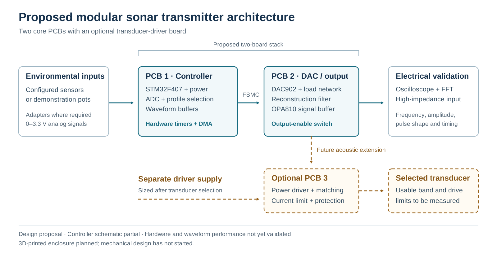
The proposed design has two boards:
- Controller board. An STM32F407 reads 3 sensor or dial inputs and picks a waveform: a chirp, a sweep or a phase-coded pulse. It streams that waveform out over a parallel bus, timed by hardware and moved by DMA.
- Output board. A 12-bit DAC902 turns the numbers into a voltage. A filter and an amplifier then smooth it for an oscilloscope.
We chose against the STM32’s built-in DAC. It takes 3–6 µs to settle after a large step, too slow for a clean 500 kHz wave.
What broke: a 50 Hz hum where speech should be
- What failed
- A recording on the ESP32-S3 showed a strong 50 Hz hum from the mains electricity instead of clean speech.
- How I found out
- Looking at which pitches were in the recording: a tall spike at 50 Hz, the frequency of mains power in India.
- What I changed
- Wrote a repeated noise-floor test and a matched power-supply A/B test, so any fix is judged before and after on the same setup. Added a 100 nF decoupling capacitor across each microphone’s power pins in the wiring guide.
- Still open
- The cause, power or grounding, is not found yet. Until it is, we do not trust any recording for SNR, STOI or PESQ.
References
- Widrow et al., Adaptive noise cancelling: principles and applications (1975)
- TinyUSB
- TI DAC902 data sheet
- STM32F407 data sheet
Credits. Arya Maddel, Jagdish Sonigra, Kashish Degaonkar, Parth Latke and Tanish Thakkar.
How I used AI tools. Reviewing code, searching for sources and drafting documents, to move faster on routine work. Every design decision is the team's, and every number here was measured or computed by us and checked by hand.